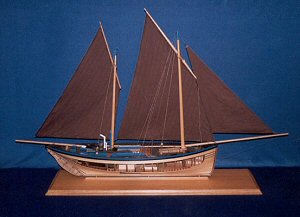
Muirneag SY486
1903-1947
Zulu-type Herring Drifter of Stornoway
in the Western Isles of Scotland
in the Western Isles of Scotland
An Exhibition-Quality Scale Model of Muirneag SY486,
Sandy MacLeod's 'Darling Girl'
Monmouth, UK
 +44(0)7791 087 525
email:
+44(0)7791 087 525
email:
Building the Model
This article appeared in Model Boats magazine, July 2005, and Model Shipwright magazine, September 2009
My fascination with model boats lies in their detail and complication, so when after a gap of 38 years I had the urge to make something nautical again, I found myself struggling against jumping in at the deep end. Wanting to build from scratch (kits are for wimps!) the question was: Sovereign of the Seas or HMS Victory? Luckily, common sense won the day - if it hadn’t, I’d still be at it now, several years later.
So, several plans catalogues further on, I wisely (or so I thought) settled on the fairly simple-looking Muirneag SY486, perhaps the most well-known of the Scottish Zulu herring drifters.
Harold Underhill’s drawings cost an arm and a leg but they were worth it, being the excellent result of a survey of the boat during her breaking up in 1947.
At 1/2" (1:24) scale she looked, well, BIG, and had a lot fewer fiddley bits than I really would have liked – and here my sensible intentions began to waver. Detail, after all, was the attraction. I’d intended to make solid frames, but the drawings were very precise about the construction of the real boat and showed a lot of the interior fittings as well, so it wasn’t long before I’d thought of making up for the rather sparse external detail by showing the inside of the boat, and wondered about leaving most of the starboard side open. However, thinking deeper into this, I realised what I’d be taking on. Because of the large scale, just about everything inside the hull would be visible, and would have to bear very close scrutiny. My not-too-complicated model was becoming more complex by the minute...
Deciding to have a go at it, I was soon stopped by the realisation that with the masts fitted she wouldn’t stand on my workshop bench because of the lowness of the ceiling. A local architect’s office solved the problem, very accurately reducing the side and plan views and the hull lines to 3/8” (1:32) scale. I could have gone smaller, but preferred to keep it a manageable size.
FRAMES
Having left the ‘simple model’ idea behind, I now found that the thing that appealed to me the most was having the opportunity to make so much of the model authentically, in much the same way as on the original boat. So the frames would be cut and jointed as closely as possible to the way they were on the old Muirneag. Feeling the need for as much information as possible, I looked far and wide for material to supplement the drawings. The National Maritime Museum had a few original prints of the boat from the 1930s, and I was supplied with pictures of another zulu, Research, being renovated at the Scottish Fisheries Museum at Anstruther. Edgar J March’s book Sailing Drifters was invaluable, although alas long out of print; my local library found me a copy which I used and coveted for over a year, hoping they’d forget about it!
I began the setting out of the frames from the lines drawing; this was something I’d never done before, and it took a long time. Harold Underhill’s Plank on Frame books were very useful here.
There are 58 frames in Muirneag’s hull, and in common with most other boats, each one is uniquely shaped. They were plotted painstakingly onto thick tracing paper, Photo 1 . The inside and outside edge bevels for the planking were also drawn, together with the scarf joint positions and drainage holes in the floors. In the larger midships section of the hull, the frames have alternately 6 and 7 parts each – floor, first futtock, second futtock (or top timber) and short timberhead – this on the real boat was for easy replacement if damaged.
At the bow and stern the frames are smaller, and have mercifully fewer parts. In the entire hull, 319 frame components, all scarf-jointed and dowelled together. The 4” thick frames scaled down exactly to 1/8” and walnut was the obvious choice for me, being close-grained, easy to work, stable and also (as a bonus) able to take a beautiful finish.
The outlines of the frame parts were transferred to the walnut sheet via old-fashioned carbon paper, some careful aligning being necessary to get the grain running along the piece (this was a virtue of the tracing paper – the timber could be seen through it) and it was possible to make use of curving grain patterns for the first and second futtocks – which ran around the sharpest curve of the hull - just as the natural shapes of the original oak board would have been utilised in the frames of the full-sized boat. This was a very time-consuming task... all first and second futtocks, floors and top timbers marked out individually with regard to grain direction, all 319 of them.
There now arose an unexpected (but rather obvious) worry. If the parts were cut to the marked lines, the tiniest inaccuracy in the fitting of the joints would put the entire frame out of shape, so I had to cut well outside the lines, leaving the final cut until after the frame was assembled. The splice joints were cut and fitted, and the most useful tool here was the disc sander. With the table set dead square with the disc, I found it relatively easy to make the joints, knowing that I only had to worry about cutting to the line on the surface, the vertical cut always being automatically square.
With the joints cut, the frames were assembled on a piece of styrene sheet, and cramped dead flat while the glue dried, Photo 2 . Very tricky, but easier the more I did. When dry, the frames were easily removed by slightly bending the sheet, and were again checked and re-marked where necessary from the tracing paper.
Cutting on the fretsaw needed great care as I felt the glued joints (mostly end-grain) were fragile, Photo 3 . As it happened only a couple of joints came apart, and when the frames were successfully rough-sawn to the final profile, each joint was drilled through and pinned with 1mm dowels, before very carefully sanding to the final profile and bevelling the inside and outside edges.
The drainage holes were drilled into the floors, and various other cosmetic things done to them; the timberheads were left overlength, to be trimmed after the deck was laid.
So the frames were completed, except for their oiled finish.
HULL ASSEMBLY JIG
As I wanted to show the interior of the starboard side, it was very important to ensure that the hull would retain its shape even though many of the starboard frames were cut away. With this sort of lop-sided construction the hull can easily pull one way or the other, and great care was taken with the assembly jig. The baseboard was 1” blockboard, with heavy MDF uprights at bow and stern and hardwood blocks to take the keel, all screwed and glued together. A piece of 4mm MDF was cut to the plan shape of the deck, screwed to a piece of timber cut to the sheer (the curved deck line in side view) and marked with the frame positions.
Slots were cut for each frame, and the whole thing screwed to the tops of the base uprights, Photo 4 . The base was also marked out with the frame positions.The keel, keelson and deadwoods (the heavy timbers which reinforce the joints between the stem, sternpost and keel) were prepared and jointed.
The cutting-in of the stern and bow keel straps was a challenge, and carried out with the knife and a miniature chisel made from an old needle file, Photo 5 . The keel assembly was put into the jig, and the long-awaited moment arrived as I began fitting the frames onto the keelson.
SETTING THE FRAMES
The first frames into the jig were the ones forming the cabin and fish-hold bulkheads with the rope-locker between them, having been first panelled with strips of cherry and assembled on the bench, then fitted as a unit into the jig because of the difficulty of getting the details in place afterwards.
The tops of these bulkheads rise above the main deck level, so I had to cut a hole in the deck jig to accommodate them, Photo 6 . Each frame was pinned through the keel, and held by wedges where they came through the jig.
On the starboard side, several whole frames were necessary to give support to the otherwise open side, and where cutaway frames were used short timberheads were wedged into the jig at deck level to take the rails and top planking. When all the frames were in place, the long job of fairing for the planking began. It was vital that the edges of the frames were perfectly in alignment with each other, because with a single-planked model you only have one chance to get the contours correct!
A block and 120 grit paper were used to remove any slight discrepancies from adjacent frames, always spanning several frames with the block and always cutting down towards the keel, never side-to-side; this ‘ripping’ with fairly coarse paper seemed a little crude, but was very successful. Finishing with fine paper (again using a block, either flat-faced or convex) gave a perfect bedding for the planks. A lot of carving was necessary where the frame floors met the keel, using various gouges and shaped sandpaper blocks on the heavy keelson and deadwoods, checking constantly with card templates cut from the frame drawings,Photo 7.
PLANKING THE HULL
For me, the most daunting part of the whole job. Having never done anything like this before, I relied heavily on the advice and experiences of others, especially (again) Harold Underhill in his Plank on Frame books, which are full of useful stuff albeit some of it a little old-fashioned now, and especially where fixings are concerned. It’s interesting to read that he dowelled everything in place, even veneers, because of his worries over adhesives!
The planks were lime, 1/16” thick to represent the original 2” larch. 3/32” square lime battens were pinned temporarily along the hull frames at various heights, to give the correct visual and actual ‘run of planking’ from stem to stern, and to act as guides for the planks. The highest batten was pinned at the position of the third plank down, and the first plank went on under this batten. The batten was then taken off and the planks above were put on, and the rail.
The rails on the zulus were just heavy planks on the outside of the frames above the wales (the heavy ‘bumpers’ running around the boat), the timberheads at the very top of the frames being left exposed. Photo 8 shows the rail pinned to each of the timberheads. Incidentally, the average height of this rail was 16” (41cm) – a very dangerous height for men working on a moving deck, often in darkness.
The planks had to be bent of course, and my method of ‘steaming’ timber is to dip the piece in water, and then to pass it through a flame, while twisting or bending it as required. And yes, he who hesitates with this method is lost... it’s very easy to scorch the timber. I believe that bent timbers should not have to be restrained by fixings but should lie more or less happily in their final positions. Harold Underhill suggests soaking or steaming the hull planks and pinning them temporarily in position until they dry out, then taking the pins out and refixing them, because the timber will have shrunk slightly during the drying process, leaving gaps between the planks. I prefer to shape timbers and dry them before fixing – this comes from my background as a joiner, where the fewer holes in the workpiece the better! I feared that with the very small movement of the plank the pin or dowel would ‘follow’ into the same hole in the frame, and I didn’t want to make another visible hole in the plank.
An advantage of the flame method is that the timber is dried in seconds, and ready to be fixed.
Sharp curves were sometimes formed over a heated bar or tube. I really should make myself a steam chamber, but as I’ve managed quite well on three other models since, I doubt I ever will!
Working down towards the keel, one plank at a time was fixed each side, taking great care to follow the line of the battens. I planed the top edge of an overwidth strip of lime to fit the bottom edge of the previous plank then cut it to width, rather than begin with a strip of the correct width, as one is expected to do with kit models. This shaping of individual planks takes up a lot of time and timber, but the results can be excellent, and it seemed the only way with planks of this size where the quality of the seams can be readily seen (in the three models I’ve since made – all from kits - the severely curved planks were cut from sheet material, which was much more work, but less hassle to my mind. I found that it often wasn’t possible to get enough taper on a 4mm wide strip, nor was it easy nor wise to try to bend it the way it didn’t want to go).
Walnut strips were placed in the planking as beds for the metal rubbing strakes, three per side - these would be visible on the inside of the planking looking through the open forecastle from the starboard side. Because of the relatively large size of the planks – average width just over 5mm – they were fairly easy to handle and cut to shape.
My favourite tool for shaping planks is an old-pattern Stanley 9.1/2 block plane; quite large I suppose, but just the right weight and I find it does exactly what I want it to. I even use it on veneer-thin 4mm wide strips.
I was able to hold each glued and pre-bent plank in place, mark it with a sharp point, then drill and dowel it to the frame without ever resorting to nails, pins or cyano glue; the dowels however needed to be a tightish fit to hold the planks firmly against the frames. PVA glue was used throughout on the planking.
The starboard side was planked except for the large open section, the edges of which would be shaped and cleaned up after sanding. It was necessary to take the hull out of the framing jig to get at the lower planks, but everything seemed very solid and stable by that time, especially as the deck jig was still in place.
I worried about removing the deck jig as there were no deck beams in place, just three bulkheads, but in the event there was none of the inwards movement I’d feared. A few deck beams were put in next, in selected positions, to give rigidity without restricting access for the interior detail. These beams were cambered, and half-housed at their ends to the frames and onto the ‘shelf’, a strip of pearwood running around the inside of the frames, visible in Photo 9.
The wales were then fitted, tight under the rails and on top of the planking. The shape of the wale is interesting, twisting from the vertical at midships to around 60º at the stern, and of course following the deck line in both planes. Again, much steam and patience. Photo 10 shows the forward end of the wale cramped in place.
The dowels for the planks were American Black Walnut, sawn to around 0.8mm square then pulled through diminishing-sized holes in a drawplate - a drilled cabinet scraper is fine for this. They finished at 0.6mm diameter, and were chopped off to 6mm long.
I later counted the dowels in the hull, and ended up cross-eyed with a total of 2,800 or so.
After the planking came the dusty job of sanding the hull. Using various shaped blocks, and progressing from 100 grit down to 240, the hull slowly revealed her curves; to view the run of the planking from stem to stern is one of the great pleasures of this business.
FINISHING THE HULL
When I was happy with the outcome (and much relieved to see just a few tiny gaps in the planking!) the ‘steam iron’ was fitted around the keel. In the full-sized boat, this 1” thick iron strip protected the keel and stem when grounding. I made it from several strips of 1/32” aluminium, pinned to the stem, keel and sternpost, with flattened ends pinned to the bow and stern breast hooks, Photo 11.
The cutout in the starboard hull planking was tidied up, along with the cut ends of the frames, and the rubbing strakes were fitted. These were from 1/8” aluminium sheet, the edge filed to half-round section then ripped off on the saw, and fixed onto the walnut bedding strips with brass pins. On the port side the rubbing strakes (and the two rows of protective iron belting on the main wale each side) are walnut. I felt a bit of a cheat, but they were to be painted anyway!
INTERIOR DETAIL
From the drawings, and the photographs of Research (at Anstruther), I had a very good record of the inside of the cabin. The first step was to form the ceiling - the boarding on the inside of the frames behind the port bunks, then the bunk bases and partitions.
The front frame with its sliding doors (not sliding on my model) was made up from strips of 0.6mm lime glued onto a base veneer, Photo 12, and fixed on top of the bench seat. The bunk mattresses were tissue paper wrapped around a flat strip of wood, and soaked with paint. The tissue expands and crumples as the paint dries, giving a good representation of bedding. The floor was boarded in cherry, and partly covered with card painted to look like linoleum. The walnut ladder, and various lockers and shelves completed the woodwork.
The donkey boiler, stove and fittings were made up from walnut, ebony and various metals, the miniature gauges and handwheel being particularly challenging, Photo 13. The handwheels (there is also one on top of the capstan) were made from 1/16” square brass, machined with a fly-cutter in the lathe to form a cross in section, then soldered to a 3/32” diameter brass ring, and turned off to leave a short pillar, Photo 14.
The fish hold was next, with its walnut stanchions and removable lime dividing boards, Photo 15. These boards gave the skipper control over where he stored his catch, and allowed him to trim the boat. The removable net platform on top of the hold held the wet nets after the fish were stored.
The forecastle shelving was meant to be full of all sorts of tackle and gear, but time caught up with me! The emptiness of these shelves however allows the frames and planks of the port side to be seen.
The mast box is framed in the middle of the floor, and allowed the foremast to lower back onto the ‘crutch’, Photo 16, when the boat was drifting with the nets out (to prevent the very heavy mainmast setting up a pendulum motion which could damage the nets).
All the interior woodwork was then given two coats of a tung-based oil, brushed on and the surplus wiped off with a rag after a few minutes - this gave a superb satin finish.
When all the interior was finished, the remaining deck beams and carlings - longitudinal beams, to take short crossbeams - were fitted, Photo 17.
The deck was planked with cherry boards, pinned with around 1,100 walnut dowels. As the boards would be painted black, the tiniest amount of chamfer was put on their edges to allow the joints to show; this is visually more satisfying than a flat, featureless expanse of deck, and gives a fair approximation of the caulking of the 2” yellow pine boards.
Photo 18 shows the forward deck being planked from the centre board outwards, after the infill margin planks were fitted between the timberheads.
The poop deck was framed up (Photo 19) and planked, and the underside which forms the cabin roof painted white, Photo 20.
EXTERNAL FITTINGS
The rudder was jointed from walnut boards and hung on pintles and straps made from brass, silver-soldered together for strength and neatness. Photo 21 shows the heel of the rudder and the keel strap.
Most of the finished brass fittings were chemically darkened to look like iron - they were submerged in old used photographic fixer (the older the better; try your local photography club, they throw the stuff away) and turned to grey/black after a few minutes. If left to harden, this chemical coating is quite tough, although a coat of matt varnish improves its durability.
The horizontal wheel was cut from a turned disc of brass, pierced and filed to shape, the small turned handles fixed on and polished, Photo 22 and Photo 23. This was a lot of very careful and difficult filing, but easier than the other methods I tried.
The steam capstan was made up from brass, stainless steel, copper, aluminium and walnut, and glued temporarily on a stick for ease of assembly and painting, Photo 24.
Photo 25 shows several of the small brass fittings, and the stages in making the main halyard sheave, which is fixed inside the bulwark to take the main halyard from the triple block to its cleat.
The chimneys for the boiler and stove were from brass tubing, silver-soldered, Photo 26.
On the foredeck the heavy, tapering ‘skegs’ which support the foremast were pinned to the deck together with their knees (Photo 27) and corresponding boltheads fitted under the deck beams, visible in Photo 28.
The nets are from net curtaining, stained black. It was difficult to find the correct scale size to correspond to the full-size mesh of 1”, Photo 29; this 1” (2.5cm) mesh would only catch fish of the correct size and maturity. The photo also shows the net floats in the side wings of the fish hold (made from beech and painted) and the loose hatch boards stacked forward of the hold. The net rope (or warp) can also be seen, going over the roller into the warp room. This rope is left-hand (cable) laid, which gives more flexibility to a large rope.
PAINTING & OILING
Much of the interior was painted or oiled before the hull was planked, which forced a strict regime of dust protection! This was nothing more than the internal spaces being filled with very soft tissue, but of course dust has a special ability where small parts are concerned, and much time was spent with a blower brush (for camera lenses) and other very small and soft brushes, cleaning out the corners.
The port side of the hull was sealed with one coat of oil, then airbrushed in Liquitex Artist’s Acrylic, which is flexible and non-fading.
A primer coat of grey, Photo 30, was followed by several coats of the correct white, brick-red and black.
For masking the white cutwater, extremely thin self-adhesive metal foil was used, and great care was needed to get the line sweeping correctly; foil isn’t the easiest thing to use, and I had to join it in several places. This was not easy, as the joins had to be perfect, Photo 31. The resulting paint edge, however, was excellent and well worth the extra effort, Photo 32.
The deck was brush painted in black - one coat only, to allow the surface texture of the planks to show through.
The vessel’s name and number were first outlined in white ink with a drawing pen, then filled in with acrylic.
With the painting done, the model was mounted temporarily on a baseboard while the masts and rigging were fitted.
MASTING & SAILS
Traditionally, Lancewood is the best timber for masts and spars but I’m told it’s virtually unobtainable now, so I bought a quite expensive piece of Lemonwood (Degame, apparently very close to Lancewood; Degame/Lemonwood is often referred to as Lancewood), which is truly wonderful for the job. It’s very close-grained, takes a beautiful finish, and most importantly stays perfectly straight.
The masts and booms were shaped by hand, tapering them first in square section and then to eight-sided and sixteen-sided, before scraping with semi-circular scrapers. They were finish-sanded with 320 grit paper, and oiled to a glass-like finish.
The sails were cotton cambric, hot-dyed, ironed flat and cut to shape using card templates. I was unhappy with my options regarding stitching, as the machine or hand stitches I was capable of would be oversize even at this scale, so I decided not to stitch the seams at all. The only hand-stitching was to fix the bolt-ropes around the outside edges of the sails.
The seams and hems were represented by strips of fabric glued to the sails with PVA. These hems were stiffened by brushing with a weak PVA solution, and when dry cut with a knife and straightedge to produce sharp edged non-fraying strips, Photo 33.
The wire luff ropes on the forward edges (the luffs) of the main and mizzen sails were served (wrapped) with yarn, on a simple contraption with rotating hooks at each end, made from plastic tubing and gears, Photo 34.
Having seen so many models with reefs sticking out unhappily at all angles from the sails, I was determined to do something better; however, try as I did, knotting them through then trying to flatten them against the sails was unsuccessful. My final method was to simply glue the dyed and knotted ropes directly to each side of the sail fabric, and I felt this was visually successful.
SUPPORTING THE MODEL
I prefer the stand/support arrangement to be discrete; all the models I’ve made have been mounted on quite delicate-looking pedestals, turned from mahogany or brass, and fixed by long screws up through the keel and into the bulkheads.
With Muirneag, I decided that something stronger was needed – the thought of my pride and joy falling of her perch was not pleasant!
The centre fixing therefore became an M5 bolt going into a threaded plate firmly fixed out of sight, between frames 23 and 24. The two other mountings are 4.5mm drill shanks, which locate into brass tubes in the hull. All a bit ‘belt and braces’ you may think, but on a biggish model it’s best to be safe.
The final touch was an etched brass nameplate giving the basic details of the boat, fixed on the baseboard off the starboard bow, Photo 35.
Having absorbed me for more than a year (2,294 hours to be very precise) both part-time and full-time, I am more than pleased with the result, and though I couldn’t afford to indulge myself in another model to this standard without having a buyer, I’m hopeful that someone will turn up before too long to put me into scratch-building mode once more!
© Gordon Williams, 2003
 top of page
My fascination with model boats lies in their detail and complication, so when after a gap of 38 years I had the urge to make something nautical again, I found myself struggling against jumping in at the deep end. Wanting to build from scratch (kits are for wimps!) the question was: Sovereign of the Seas or HMS Victory? Luckily, common sense won the day - if it hadn’t, I’d still be at it now, several years later.
So, several plans catalogues further on, I wisely (or so I thought) settled on the fairly simple-looking Muirneag SY486, perhaps the most well-known of the Scottish Zulu herring drifters.
Harold Underhill’s drawings cost an arm and a leg but they were worth it, being the excellent result of a survey of the boat during her breaking up in 1947.
At 1/2" (1:24) scale she looked, well, BIG, and had a lot fewer fiddley bits than I really would have liked – and here my sensible intentions began to waver. Detail, after all, was the attraction. I’d intended to make solid frames, but the drawings were very precise about the construction of the real boat and showed a lot of the interior fittings as well, so it wasn’t long before I’d thought of making up for the rather sparse external detail by showing the inside of the boat, and wondered about leaving most of the starboard side open. However, thinking deeper into this, I realised what I’d be taking on. Because of the large scale, just about everything inside the hull would be visible, and would have to bear very close scrutiny. My not-too-complicated model was becoming more complex by the minute...
Deciding to have a go at it, I was soon stopped by the realisation that with the masts fitted she wouldn’t stand on my workshop bench because of the lowness of the ceiling. A local architect’s office solved the problem, very accurately reducing the side and plan views and the hull lines to 3/8” (1:32) scale. I could have gone smaller, but preferred to keep it a manageable size.
FRAMES
Having left the ‘simple model’ idea behind, I now found that the thing that appealed to me the most was having the opportunity to make so much of the model authentically, in much the same way as on the original boat. So the frames would be cut and jointed as closely as possible to the way they were on the old Muirneag. Feeling the need for as much information as possible, I looked far and wide for material to supplement the drawings. The National Maritime Museum had a few original prints of the boat from the 1930s, and I was supplied with pictures of another zulu, Research, being renovated at the Scottish Fisheries Museum at Anstruther. Edgar J March’s book Sailing Drifters was invaluable, although alas long out of print; my local library found me a copy which I used and coveted for over a year, hoping they’d forget about it!
I began the setting out of the frames from the lines drawing; this was something I’d never done before, and it took a long time. Harold Underhill’s Plank on Frame books were very useful here.
There are 58 frames in Muirneag’s hull, and in common with most other boats, each one is uniquely shaped. They were plotted painstakingly onto thick tracing paper, Photo 1 . The inside and outside edge bevels for the planking were also drawn, together with the scarf joint positions and drainage holes in the floors. In the larger midships section of the hull, the frames have alternately 6 and 7 parts each – floor, first futtock, second futtock (or top timber) and short timberhead – this on the real boat was for easy replacement if damaged.
At the bow and stern the frames are smaller, and have mercifully fewer parts. In the entire hull, 319 frame components, all scarf-jointed and dowelled together. The 4” thick frames scaled down exactly to 1/8” and walnut was the obvious choice for me, being close-grained, easy to work, stable and also (as a bonus) able to take a beautiful finish.
The outlines of the frame parts were transferred to the walnut sheet via old-fashioned carbon paper, some careful aligning being necessary to get the grain running along the piece (this was a virtue of the tracing paper – the timber could be seen through it) and it was possible to make use of curving grain patterns for the first and second futtocks – which ran around the sharpest curve of the hull - just as the natural shapes of the original oak board would have been utilised in the frames of the full-sized boat. This was a very time-consuming task... all first and second futtocks, floors and top timbers marked out individually with regard to grain direction, all 319 of them.
There now arose an unexpected (but rather obvious) worry. If the parts were cut to the marked lines, the tiniest inaccuracy in the fitting of the joints would put the entire frame out of shape, so I had to cut well outside the lines, leaving the final cut until after the frame was assembled. The splice joints were cut and fitted, and the most useful tool here was the disc sander. With the table set dead square with the disc, I found it relatively easy to make the joints, knowing that I only had to worry about cutting to the line on the surface, the vertical cut always being automatically square.
With the joints cut, the frames were assembled on a piece of styrene sheet, and cramped dead flat while the glue dried, Photo 2 . Very tricky, but easier the more I did. When dry, the frames were easily removed by slightly bending the sheet, and were again checked and re-marked where necessary from the tracing paper.
Cutting on the fretsaw needed great care as I felt the glued joints (mostly end-grain) were fragile, Photo 3 . As it happened only a couple of joints came apart, and when the frames were successfully rough-sawn to the final profile, each joint was drilled through and pinned with 1mm dowels, before very carefully sanding to the final profile and bevelling the inside and outside edges.
The drainage holes were drilled into the floors, and various other cosmetic things done to them; the timberheads were left overlength, to be trimmed after the deck was laid.
So the frames were completed, except for their oiled finish.
HULL ASSEMBLY JIG
As I wanted to show the interior of the starboard side, it was very important to ensure that the hull would retain its shape even though many of the starboard frames were cut away. With this sort of lop-sided construction the hull can easily pull one way or the other, and great care was taken with the assembly jig. The baseboard was 1” blockboard, with heavy MDF uprights at bow and stern and hardwood blocks to take the keel, all screwed and glued together. A piece of 4mm MDF was cut to the plan shape of the deck, screwed to a piece of timber cut to the sheer (the curved deck line in side view) and marked with the frame positions.
Slots were cut for each frame, and the whole thing screwed to the tops of the base uprights, Photo 4 . The base was also marked out with the frame positions.The keel, keelson and deadwoods (the heavy timbers which reinforce the joints between the stem, sternpost and keel) were prepared and jointed.
The cutting-in of the stern and bow keel straps was a challenge, and carried out with the knife and a miniature chisel made from an old needle file, Photo 5 . The keel assembly was put into the jig, and the long-awaited moment arrived as I began fitting the frames onto the keelson.
SETTING THE FRAMES
The first frames into the jig were the ones forming the cabin and fish-hold bulkheads with the rope-locker between them, having been first panelled with strips of cherry and assembled on the bench, then fitted as a unit into the jig because of the difficulty of getting the details in place afterwards.
The tops of these bulkheads rise above the main deck level, so I had to cut a hole in the deck jig to accommodate them, Photo 6 . Each frame was pinned through the keel, and held by wedges where they came through the jig.
On the starboard side, several whole frames were necessary to give support to the otherwise open side, and where cutaway frames were used short timberheads were wedged into the jig at deck level to take the rails and top planking. When all the frames were in place, the long job of fairing for the planking began. It was vital that the edges of the frames were perfectly in alignment with each other, because with a single-planked model you only have one chance to get the contours correct!
A block and 120 grit paper were used to remove any slight discrepancies from adjacent frames, always spanning several frames with the block and always cutting down towards the keel, never side-to-side; this ‘ripping’ with fairly coarse paper seemed a little crude, but was very successful. Finishing with fine paper (again using a block, either flat-faced or convex) gave a perfect bedding for the planks. A lot of carving was necessary where the frame floors met the keel, using various gouges and shaped sandpaper blocks on the heavy keelson and deadwoods, checking constantly with card templates cut from the frame drawings,Photo 7.
PLANKING THE HULL
For me, the most daunting part of the whole job. Having never done anything like this before, I relied heavily on the advice and experiences of others, especially (again) Harold Underhill in his Plank on Frame books, which are full of useful stuff albeit some of it a little old-fashioned now, and especially where fixings are concerned. It’s interesting to read that he dowelled everything in place, even veneers, because of his worries over adhesives!
The planks were lime, 1/16” thick to represent the original 2” larch. 3/32” square lime battens were pinned temporarily along the hull frames at various heights, to give the correct visual and actual ‘run of planking’ from stem to stern, and to act as guides for the planks. The highest batten was pinned at the position of the third plank down, and the first plank went on under this batten. The batten was then taken off and the planks above were put on, and the rail.
The rails on the zulus were just heavy planks on the outside of the frames above the wales (the heavy ‘bumpers’ running around the boat), the timberheads at the very top of the frames being left exposed. Photo 8 shows the rail pinned to each of the timberheads. Incidentally, the average height of this rail was 16” (41cm) – a very dangerous height for men working on a moving deck, often in darkness.
The planks had to be bent of course, and my method of ‘steaming’ timber is to dip the piece in water, and then to pass it through a flame, while twisting or bending it as required. And yes, he who hesitates with this method is lost... it’s very easy to scorch the timber. I believe that bent timbers should not have to be restrained by fixings but should lie more or less happily in their final positions. Harold Underhill suggests soaking or steaming the hull planks and pinning them temporarily in position until they dry out, then taking the pins out and refixing them, because the timber will have shrunk slightly during the drying process, leaving gaps between the planks. I prefer to shape timbers and dry them before fixing – this comes from my background as a joiner, where the fewer holes in the workpiece the better! I feared that with the very small movement of the plank the pin or dowel would ‘follow’ into the same hole in the frame, and I didn’t want to make another visible hole in the plank.
An advantage of the flame method is that the timber is dried in seconds, and ready to be fixed.
Sharp curves were sometimes formed over a heated bar or tube. I really should make myself a steam chamber, but as I’ve managed quite well on three other models since, I doubt I ever will!
Working down towards the keel, one plank at a time was fixed each side, taking great care to follow the line of the battens. I planed the top edge of an overwidth strip of lime to fit the bottom edge of the previous plank then cut it to width, rather than begin with a strip of the correct width, as one is expected to do with kit models. This shaping of individual planks takes up a lot of time and timber, but the results can be excellent, and it seemed the only way with planks of this size where the quality of the seams can be readily seen (in the three models I’ve since made – all from kits - the severely curved planks were cut from sheet material, which was much more work, but less hassle to my mind. I found that it often wasn’t possible to get enough taper on a 4mm wide strip, nor was it easy nor wise to try to bend it the way it didn’t want to go).
Walnut strips were placed in the planking as beds for the metal rubbing strakes, three per side - these would be visible on the inside of the planking looking through the open forecastle from the starboard side. Because of the relatively large size of the planks – average width just over 5mm – they were fairly easy to handle and cut to shape.
My favourite tool for shaping planks is an old-pattern Stanley 9.1/2 block plane; quite large I suppose, but just the right weight and I find it does exactly what I want it to. I even use it on veneer-thin 4mm wide strips.
I was able to hold each glued and pre-bent plank in place, mark it with a sharp point, then drill and dowel it to the frame without ever resorting to nails, pins or cyano glue; the dowels however needed to be a tightish fit to hold the planks firmly against the frames. PVA glue was used throughout on the planking.
The starboard side was planked except for the large open section, the edges of which would be shaped and cleaned up after sanding. It was necessary to take the hull out of the framing jig to get at the lower planks, but everything seemed very solid and stable by that time, especially as the deck jig was still in place.
I worried about removing the deck jig as there were no deck beams in place, just three bulkheads, but in the event there was none of the inwards movement I’d feared. A few deck beams were put in next, in selected positions, to give rigidity without restricting access for the interior detail. These beams were cambered, and half-housed at their ends to the frames and onto the ‘shelf’, a strip of pearwood running around the inside of the frames, visible in Photo 9.
The wales were then fitted, tight under the rails and on top of the planking. The shape of the wale is interesting, twisting from the vertical at midships to around 60º at the stern, and of course following the deck line in both planes. Again, much steam and patience. Photo 10 shows the forward end of the wale cramped in place.
The dowels for the planks were American Black Walnut, sawn to around 0.8mm square then pulled through diminishing-sized holes in a drawplate - a drilled cabinet scraper is fine for this. They finished at 0.6mm diameter, and were chopped off to 6mm long.
I later counted the dowels in the hull, and ended up cross-eyed with a total of 2,800 or so.
After the planking came the dusty job of sanding the hull. Using various shaped blocks, and progressing from 100 grit down to 240, the hull slowly revealed her curves; to view the run of the planking from stem to stern is one of the great pleasures of this business.
FINISHING THE HULL
When I was happy with the outcome (and much relieved to see just a few tiny gaps in the planking!) the ‘steam iron’ was fitted around the keel. In the full-sized boat, this 1” thick iron strip protected the keel and stem when grounding. I made it from several strips of 1/32” aluminium, pinned to the stem, keel and sternpost, with flattened ends pinned to the bow and stern breast hooks, Photo 11.
The cutout in the starboard hull planking was tidied up, along with the cut ends of the frames, and the rubbing strakes were fitted. These were from 1/8” aluminium sheet, the edge filed to half-round section then ripped off on the saw, and fixed onto the walnut bedding strips with brass pins. On the port side the rubbing strakes (and the two rows of protective iron belting on the main wale each side) are walnut. I felt a bit of a cheat, but they were to be painted anyway!
INTERIOR DETAIL
From the drawings, and the photographs of Research (at Anstruther), I had a very good record of the inside of the cabin. The first step was to form the ceiling - the boarding on the inside of the frames behind the port bunks, then the bunk bases and partitions.
The front frame with its sliding doors (not sliding on my model) was made up from strips of 0.6mm lime glued onto a base veneer, Photo 12, and fixed on top of the bench seat. The bunk mattresses were tissue paper wrapped around a flat strip of wood, and soaked with paint. The tissue expands and crumples as the paint dries, giving a good representation of bedding. The floor was boarded in cherry, and partly covered with card painted to look like linoleum. The walnut ladder, and various lockers and shelves completed the woodwork.
The donkey boiler, stove and fittings were made up from walnut, ebony and various metals, the miniature gauges and handwheel being particularly challenging, Photo 13. The handwheels (there is also one on top of the capstan) were made from 1/16” square brass, machined with a fly-cutter in the lathe to form a cross in section, then soldered to a 3/32” diameter brass ring, and turned off to leave a short pillar, Photo 14.
The fish hold was next, with its walnut stanchions and removable lime dividing boards, Photo 15. These boards gave the skipper control over where he stored his catch, and allowed him to trim the boat. The removable net platform on top of the hold held the wet nets after the fish were stored.
The forecastle shelving was meant to be full of all sorts of tackle and gear, but time caught up with me! The emptiness of these shelves however allows the frames and planks of the port side to be seen.
The mast box is framed in the middle of the floor, and allowed the foremast to lower back onto the ‘crutch’, Photo 16, when the boat was drifting with the nets out (to prevent the very heavy mainmast setting up a pendulum motion which could damage the nets).
All the interior woodwork was then given two coats of a tung-based oil, brushed on and the surplus wiped off with a rag after a few minutes - this gave a superb satin finish.
When all the interior was finished, the remaining deck beams and carlings - longitudinal beams, to take short crossbeams - were fitted, Photo 17.
The deck was planked with cherry boards, pinned with around 1,100 walnut dowels. As the boards would be painted black, the tiniest amount of chamfer was put on their edges to allow the joints to show; this is visually more satisfying than a flat, featureless expanse of deck, and gives a fair approximation of the caulking of the 2” yellow pine boards.
Photo 18 shows the forward deck being planked from the centre board outwards, after the infill margin planks were fitted between the timberheads.
The poop deck was framed up (Photo 19) and planked, and the underside which forms the cabin roof painted white, Photo 20.
EXTERNAL FITTINGS
The rudder was jointed from walnut boards and hung on pintles and straps made from brass, silver-soldered together for strength and neatness. Photo 21 shows the heel of the rudder and the keel strap.
Most of the finished brass fittings were chemically darkened to look like iron - they were submerged in old used photographic fixer (the older the better; try your local photography club, they throw the stuff away) and turned to grey/black after a few minutes. If left to harden, this chemical coating is quite tough, although a coat of matt varnish improves its durability.
The horizontal wheel was cut from a turned disc of brass, pierced and filed to shape, the small turned handles fixed on and polished, Photo 22 and Photo 23. This was a lot of very careful and difficult filing, but easier than the other methods I tried.
The steam capstan was made up from brass, stainless steel, copper, aluminium and walnut, and glued temporarily on a stick for ease of assembly and painting, Photo 24.
Photo 25 shows several of the small brass fittings, and the stages in making the main halyard sheave, which is fixed inside the bulwark to take the main halyard from the triple block to its cleat.
The chimneys for the boiler and stove were from brass tubing, silver-soldered, Photo 26.
On the foredeck the heavy, tapering ‘skegs’ which support the foremast were pinned to the deck together with their knees (Photo 27) and corresponding boltheads fitted under the deck beams, visible in Photo 28.
The nets are from net curtaining, stained black. It was difficult to find the correct scale size to correspond to the full-size mesh of 1”, Photo 29; this 1” (2.5cm) mesh would only catch fish of the correct size and maturity. The photo also shows the net floats in the side wings of the fish hold (made from beech and painted) and the loose hatch boards stacked forward of the hold. The net rope (or warp) can also be seen, going over the roller into the warp room. This rope is left-hand (cable) laid, which gives more flexibility to a large rope.
PAINTING & OILING
Much of the interior was painted or oiled before the hull was planked, which forced a strict regime of dust protection! This was nothing more than the internal spaces being filled with very soft tissue, but of course dust has a special ability where small parts are concerned, and much time was spent with a blower brush (for camera lenses) and other very small and soft brushes, cleaning out the corners.
The port side of the hull was sealed with one coat of oil, then airbrushed in Liquitex Artist’s Acrylic, which is flexible and non-fading.
A primer coat of grey, Photo 30, was followed by several coats of the correct white, brick-red and black.
For masking the white cutwater, extremely thin self-adhesive metal foil was used, and great care was needed to get the line sweeping correctly; foil isn’t the easiest thing to use, and I had to join it in several places. This was not easy, as the joins had to be perfect, Photo 31. The resulting paint edge, however, was excellent and well worth the extra effort, Photo 32.
The deck was brush painted in black - one coat only, to allow the surface texture of the planks to show through.
The vessel’s name and number were first outlined in white ink with a drawing pen, then filled in with acrylic.
With the painting done, the model was mounted temporarily on a baseboard while the masts and rigging were fitted.
MASTING & SAILS
Traditionally, Lancewood is the best timber for masts and spars but I’m told it’s virtually unobtainable now, so I bought a quite expensive piece of Lemonwood (Degame, apparently very close to Lancewood; Degame/Lemonwood is often referred to as Lancewood), which is truly wonderful for the job. It’s very close-grained, takes a beautiful finish, and most importantly stays perfectly straight.
The masts and booms were shaped by hand, tapering them first in square section and then to eight-sided and sixteen-sided, before scraping with semi-circular scrapers. They were finish-sanded with 320 grit paper, and oiled to a glass-like finish.
The sails were cotton cambric, hot-dyed, ironed flat and cut to shape using card templates. I was unhappy with my options regarding stitching, as the machine or hand stitches I was capable of would be oversize even at this scale, so I decided not to stitch the seams at all. The only hand-stitching was to fix the bolt-ropes around the outside edges of the sails.
The seams and hems were represented by strips of fabric glued to the sails with PVA. These hems were stiffened by brushing with a weak PVA solution, and when dry cut with a knife and straightedge to produce sharp edged non-fraying strips, Photo 33.
The wire luff ropes on the forward edges (the luffs) of the main and mizzen sails were served (wrapped) with yarn, on a simple contraption with rotating hooks at each end, made from plastic tubing and gears, Photo 34.
Having seen so many models with reefs sticking out unhappily at all angles from the sails, I was determined to do something better; however, try as I did, knotting them through then trying to flatten them against the sails was unsuccessful. My final method was to simply glue the dyed and knotted ropes directly to each side of the sail fabric, and I felt this was visually successful.
SUPPORTING THE MODEL
I prefer the stand/support arrangement to be discrete; all the models I’ve made have been mounted on quite delicate-looking pedestals, turned from mahogany or brass, and fixed by long screws up through the keel and into the bulkheads.
With Muirneag, I decided that something stronger was needed – the thought of my pride and joy falling of her perch was not pleasant!
The centre fixing therefore became an M5 bolt going into a threaded plate firmly fixed out of sight, between frames 23 and 24. The two other mountings are 4.5mm drill shanks, which locate into brass tubes in the hull. All a bit ‘belt and braces’ you may think, but on a biggish model it’s best to be safe.
The final touch was an etched brass nameplate giving the basic details of the boat, fixed on the baseboard off the starboard bow, Photo 35.
Having absorbed me for more than a year (2,294 hours to be very precise) both part-time and full-time, I am more than pleased with the result, and though I couldn’t afford to indulge myself in another model to this standard without having a buyer, I’m hopeful that someone will turn up before too long to put me into scratch-building mode once more!
© Gordon Williams, 2003
top of page
http://www.muirneag.net/article.html
© Gordon Williams 2013
Last revised 8th February 2013
W3C Valid XHTML and CSS